Its hard to explain how hard to teach programming without a proper computer. Base on Tiny Basic student should be able to learn basic skill of programming with minimal budget. here is the source code
This is first club's activity after Covid-19 lock-down. hope you are doing well. Will update part 2 soon
BRYMEN BM867s Data Logging
BRYMEN BM867 usb interface kit data logging and pc connection. basically they can display everything what you can see on multimeter screen on PC plus they can capture and record the data in pc storage.
the only used one usb microcontroller. put them in the case with $40 price tag.
ADALM2000 vs ANALOG DISCOVERY 2
Have you ever think to have all lab equipment in you backpack? Now you can. Despite ADALM2000 way more cheaper than their sibling. Its has very good power supply too. Other functionality pretty much the same.
Two-channel USB digital oscilloscope
Two-channel arbitrary function generator
16-channel digital logic analyzer (3.3V CMOS and 1.8V or 5V tolerant, 100MS/s)
16-channel pattern generator (3.3V CMOS, 100MS/s)
16-channel virtual digital I/O
Two input/output digital trigger signals for linking multiple instruments (3.3V CMOS)
Single channel voltmeter (AC, DC, ±20V)
Network analyzer – Bode, Nyquist, Nichols transfer diagrams of a circuit. Range: 1Hz to 10MHz
Spectrum Analyzer – power spectrum and spectral measurements (noise floor, SFDR, SNR, THD, etc.)
Digital Bus Analyzers (SPI, I²C, UART, Parallel)
Two programmable power supplies (0…+5V , 0…-5V)
The only difference might be AD2 more pupular than other. some people (student) might never heard of ADALM2000. here is the video of my simple test on built-in psu in ADALM2000 compare to well know instrument meter. FLUKE8846A and Brymen 867S
DC load for our STEM lab
Other than oscilloscope Programmable DC Load are the most important device in any STEM lab. It was used in many testing and troubleshooting of power related equipment for example power supply, solar panel and batteries. But it would cost you a lot of money to get a precision one. So we have decide to built one from scratch. Start with simple circuit only 2 component. we will built up our circuit from there. After spending hours in front of scope try to get what is the best setting not to burn our mosfet here is what we get.
At first attempt. We found that our stock mosfet IRL3302 are not design to handle linear (saturation) current very well continuously. It was design to be use in switching mode which (below 10ms pulse). Mosfet tend to heating up so fast even with significantly low current 2A at 9V. In the world of DC load 2A is consider low since the your target is 5A at 30V or 150W at least.
Next step we try to vary the input and capture the outcome from the scope. Probe A of oscilloscope are connected to pulse generator at 10kHz pwm with duty around 30% and connected directly to Gate pin of our mosfet.
here is the basic setting of our pulse gen.
Freq: 31Khz
Duty: 50%
Amplitude: 5V (from 0v )
From the picture above blue line shows the input of the pulse. The red line shows the current Ids (we tap the second channel of our scope to 1 ohm resistor. So theoretically we get 1.0V every 1.0A of Ids. By using the pulse we significantly reduce the amount of heat produce by mosfet. Around 37 deg C for 5 minute of running time. The load resistor temp increase up to 70 deg C.
Mosfet temperature reading
Load resistor temperature reading
The second problem of our circuit is the output of mosfet is ringing and avalanche energy from inductive load (wire-wound load resistor) could damage the mosfet. As you can see in the scope below there are spike around 50uS before settle at the targeted amperage on falling and rising edge.
RC Snubber will be added in parallel to the output of mosfet between drain and source. in order to reduce the ringing effect. here is the formula we use to calculate the value of capacitance and resistance.
where Fp is ringing frequency you get from scope, Cp is parasitic capacitance can be refer as Coss from data sheet as shown below.
(problem with my scope - after updating to PicoScope6_r6_14_4.exe)
We change our long service Picoscope 3205 to all in one scope from Analog Device ADALM2000. With 12-bit ADCs and DACs running at 100 MSPS, the M2K brings the power of high performance lab equipment. Here is the picture of the device and some Lissajous plot from the device. If you ever tried Analog Discovery 2 then this is the alternative with half of the price.
Here is a little detail about ADALM2000.
Two-channel USB digital oscilloscope
Two-channel arbitrary function generator
16-channel digital logic analyzer (3.3V CMOS and 1.8V or 5V tolerant, 100MS/s)
16-channel pattern generator (3.3V CMOS, 100MS/s)
16-channel virtual digital I/O
Two input/output digital trigger signals for linking multiple instruments (3.3V CMOS)
Single channel voltmeter (AC, DC, ±20V)
Network analyzer – Bode, Nyquist, Nichols transfer diagrams of a circuit. Range: 1Hz to 10MHz
Spectrum Analyzer – power spectrum and spectral measurements (noise floor, SFDR, SNR, THD, etc.)
Digital Bus Analyzers (SPI, I²C, UART, Parallel)
Two programmable power supplies (0…+5V , 0…-5V)
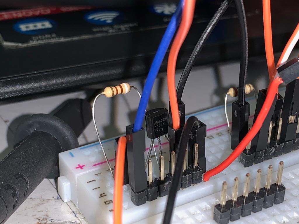
Ok back to our DC Load project. In order to maintain the current while battery voltage is dropping we need a feedback a mechanism to decrease the resistance of mosfet. so that it will maintains the constant current. We have to use an op amp to this job. we will need something like voltage follower or buffer to give us feedback. We also have to provide accurate and stable voltage input to op amp so that they will not change the output due to system ripple and any noise possible. here is what we do.
-DAC MCP4725
-Vref LM4040- 4.096V
As you can see ADALM2000 give pretty accurate DCV reading and comparable with Brymen BM87s.