Most of the problem in robotic are coming from driving the motor itself. Instead of creating our version of H bridge driver we just let professional do it for us. We are not going to re-invent the wheel here. The right answer for our problem is Sabertooth 2x32. Sabertooth 2x32 is a dual channel motor driver capable of supplying 32 amps to two motors, with peak currents up to 64 amps per motor. It can be operated from radio control, analog, TTL serial or USB inputs. It uses regenerative drive and braking for efficient operation. A variety of operating modes including tank style mixing and automatic calibration allow most projects to work immediately out of the box. When combined with Dimension Engineering’s Kangaroo x2 motion control module, the Sabertooth 2x32 can be used for closed-loop position or speed control with encoder or analog feedback. The state of the driver can be monitored in real time using the USB port in any operating mode, making debugging your project faster and easier. Sabertooth 2x32 is more flexible, robust and powerful than previous motor drivers, while also being easier to use.


Main Power Input: Connect to a 6V-33.6V Battery or Power Supply.
Motor 1 and Motor 2: Connect Motor 1 to the M1A and M1B. Connect Motor 2 to M2A and M2B.
DIP Switches: These are used to set the operating mode and options. Can be changed while operating.
USB: A standard Micro USB port. Connect to a PC or other USB host to control, monitor or modify.
Logic Ground: The 0V logic ground is connected internally to B-.
5V Output: 5V is a regulated 5 volt output. You can use it to power additional circuitry up to 1 amp.
Main Signal Inputs: Connect your main analog, R/C or serial signals here.
Aux Signal Inputs: These may be used for additional control. Optional in most modes.
Power Outputs: These connect to voltage clamp resistors, electromagnetic brakes, field windings, or other moderate power loads. 8A max current per channel.
Status and Error LEDs: These glow and flash to indicate the status of the Sabertooth 2x32.

Sabertooth 2x32 has four logic inputs S1, S2, A1 and A2. The analog input range is 0 to 5 volts. Digital signals can be 3, 3.3 or 5v logic. All third generation drivers such as Sabertooth 2x32 include a USB port. The USB port can be used for control from a PC or embedded processor like a Raspberry Pi. It can also be used to monitor the inputs and outputs, set up user modes and custom settings, and update the firmware.
Outputs
Sabertooth 2x32 is a dual motor driver, and can drive two motors at up to 32 amps continuous and 64 amps peak current per channel. In addition, there are two 8 amp auxiliary outputs and two 20 milliamp indicator outputs.

Motor Outputs
Sabertooth 2x32’s M1 and M2 motor outputs are 12 bit, synchronous regenerative motor drives. They have a switching frequency of 30 kHz for silent operation. Each channel has a programmable current limit. It is also possible to disable regeneration to drive loads like lamps or anodizing tanks, or completely disable the outputs and braking to allow motors to freewheel.
Typical motors used with a Sabertooth 2x32 include fractional horsepower permanent magnet motors, wheelchair type motors, scooter type motors and brush type cordless tool motors. Most two wire, permanent magnet motors can be made to work. Sabertooth motor drives have also been used to drive large solenoids, lamps, heaters, coolers, electromagnets, shakers and transducers. To minimize heating and losses, use as large a wire to your motors as is practical. 12 gauge is typical for short wiring runs.


Indicator Outputs
Two of the signal inputs, S2 and A2, can be used as 20 milliamp, 3.3 volt outputs. This is typically used to drive LEDs for remote control panels or signal back to microcontrollers. The indicator outputs are secondary functions of the S2 and A2 inputs. When in indicator mode, these pins have a built-in 220 ohm series resistor, so they can drive loads directly.
Power Outputs
These open collector outputs can sink up to 8 amps of current each. The power outputs can be configured as Voltage Clamps, Brakes or Controllable Outputs.

Control Modes
Sabertooth 2x32 has four main control modes, plus a special User mode that can be used to create custom control modes. Control Modes are selected via the six DIP switches. DIP switches 1 and 2 select the control mode, and DIP switches 4, 5 and 6 select the options within each control mode.
Analog
Analog control uses analog voltages to send commands to the Sabertooth 2x32. This is the simplest way to control a Sabertooth. These voltages can be generated by potentiometers, switches, joysticks or digital to analog converters. The input voltage range is 0 volts to 5 volts. Custom ranges can be set using the DEScribe PC software. In Analog the S1, S2, A1 and A2 terminals are analog inputs. They are internally pulled down to 0V if not connected to a signal.
Radio Control
Radio Control uses R/C (servo) pulses to send commands to the Sabertooth 2x32. These signals are generated by R/C transmitters and receivers, or by microcontrollers. Anything that can generate servo signals can be used to drive a Sabertooth in Radio Control mode. In Radio Control mode the S1, S2, and A2 inputs are set up to read R/C pulses. The A1 input is set up as an analog input and can be used with a potentiometer for an adjustable ramp rate.


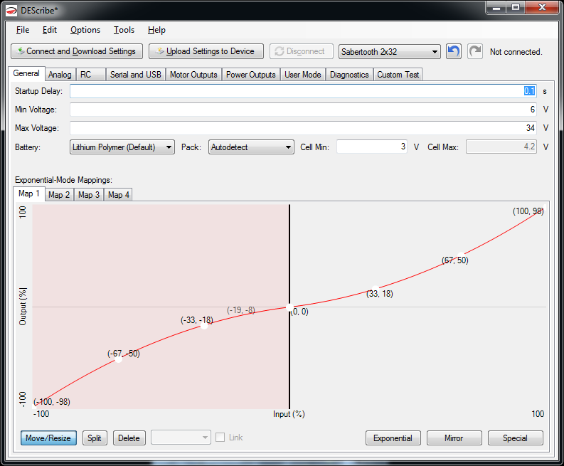
Exponential-Mode Mappings
Sabertooth 2x32 can have up to four maps which modify the ratio of input signal to output signal. These can be used to add a deadband, change the responsiveness of the system, make the Sabertooth only turn the motors one way, or other uses. Each exponential map is defined by a series of curves. Each curve is defined by control points. By clicking and dragging the control points, you can change the shape of the curve. Which exponential map is used for each output is selected with DIP switches and/or settings in that operating mode’s tab in DEScribe.
Most of the time, what you want is a certain percentage of exponential and a certain amount of deadband where the motor output is off. These can be handled automatically. Clicking the Exponential button in the bottom right corner of the window will bring up the Exponential Curve window. By dragging the sliders, the currently tabbed exponential map can be modified with little effort.
For more customized maps, you may have to add additional segments. To break a segment into two smaller segments, select the Split tool at the bottom, then click on the curve you wish to divide. The start and end of the curves can be changed by clicking the black vertical divider bars and dragging right or left. To remove a segment, select the Delete tool and click on the segment you wish to remove. To change the curve type, select the segment and change the dropdown from Curve to Linear or Constant. If you have created a custom exponential map, it is often a good idea to save your settings file for re-use later. To save a settings file, click File… Save and create a file name.
There are four maps. By default, Exponential mode uses Map 1 for both channels, so it is usually the only one that needs to be modified. Maps can be modified even if they are not currently being used.

hai.kat malaysia ada jual tak
ReplyDelete012 5573717
Di Malaysia ada jual ndak?
ReplyDeleteMalaysia mana nak cari driver ni
ReplyDeletesaya order USA
ReplyDelete